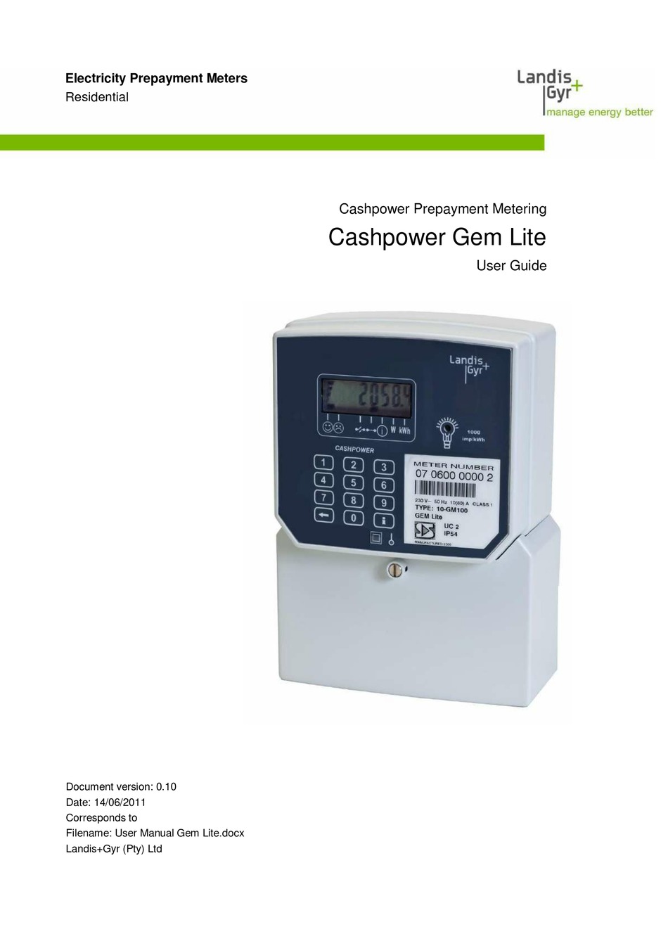


Save my name, email, and website in this browser for the next time I comment. Please Contact us for pricing and availability. This product is available but no longer a stock item. Apart from the common terminal layout according to DIN the ZMD meters are also available optionally with symmetrical terminal layout.įigure Figure Connection diagram of measuring unit ZMDxT with current transformer symmetrical terminal layout Figure The E meter may be utilised in an off-line mode as a stand-alone split prepayment meter, or in an on-line mode as part of an end to end two way AMI smart metering solution. Page Connections Two utility seals in the fixing screws of the terminal cover prevent unauthorised access to the phase connections and therefore also prevent unrecorded energy consumption.

Landis and gyr meter manual serial#
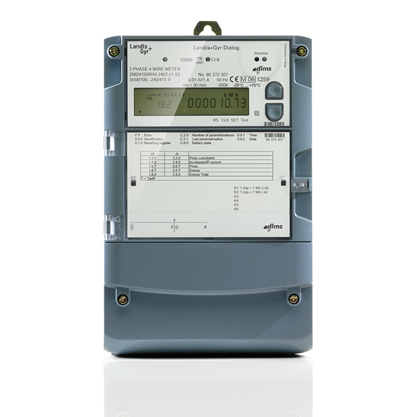
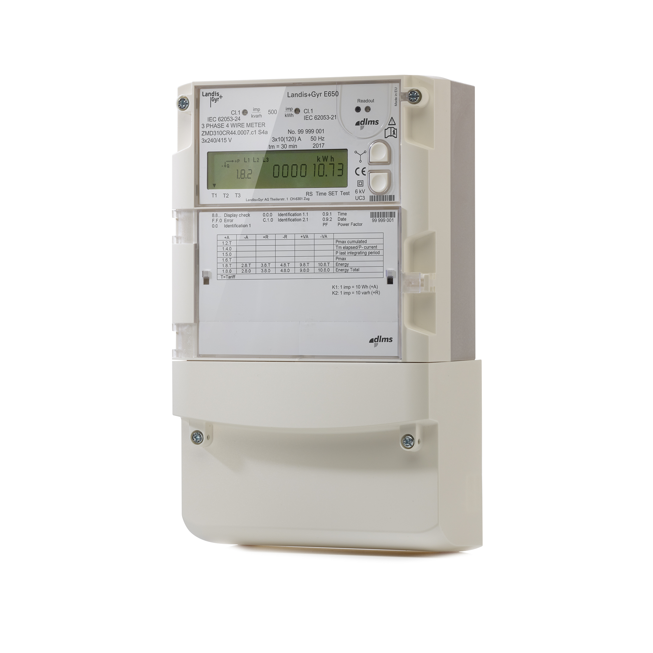
Page Faceplates 15 Meter data type designation, serial number, rated values, year of manufacture 16 Reference to reactive energy standard 17 Alarm LED optional The operating elements and displays are described more detailed in section 5 "Operation". The two bulges firmly fix the seal component into the lateral grooves. Figure Now turn the seal component until it is horizontal and slide it down into position 2 as illustrated. The lower part of the case is additionally glass-fibre reinforced. Page Mechanical Construction top and the tariff faceplate bottom. With DC magnet detection, it is possible to order the integrated terminal cover detection option. Page Communication It can be fitted and removed at any time in the field without touching the certification seal. Events which can be stored in the dedicated event log are marked in the corresponding column. Page Event Log Depending on the parameterisation, some events may never occur. Consult your sales representative for further details. Page Summation Channels The measured values that are captured in the load profile can be selected by parameterisation. If this option is chosen, NLA and OLA losses are not available any more as these registers are used for signed losses. Case 1: All voltage and current angles are displayed clockwise with reference to the voltage in phase 1. The times between zero passage of the phase voltage U1 and those of the other phase voltages U2 and U3 serves to determine the phase angle between the voltages and of the rotating field. Page Signal Processor Thereby the harmonics up to 1 kHz are measured correctly.
Landis and gyr meter manual series#
S4s represents a Series 4 meter with symmetrical terminal layout. An attached suffix points out that the meter is equipped with certain non-standard features, e.

: Device Description With a communication unit, the meters can also be used for recording counter pulses for other physical media e. For maximum currents of auxiliary terminals, see section 4. : Safety-related Meter Data For nominal reference voltage and current, see the nameplate of the meter. In a domestic environment, this may then cause radio interference, in which case the user may be required to take adequate measures. Connection to medium and high voltage t - Mounting the meter - Connecting the meter - Connecting the phase connection lines - Connecting the signal inputs and outputs - Maximum current of auxiliary current out - Connection of active inputs - Commissioning, functional check and seal Quick Links.ĭownload this manual.


 0 kommentar(er)
